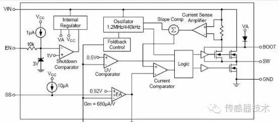
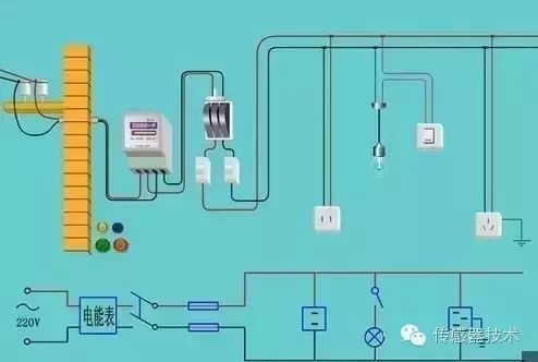
As an engineer engaged in hardware design work, we must first have excellent basic skills. We must be able to have a general understanding of circuit schematics with technical parameters. We can divide function modules, find out the flow of signals, and determine the role of components. When the circuit is analyzed, the actual working condition of the circuit can be understood by recognizing the symbols of the various circuit components drawn on the drawings and the connections between them. The following figure shows the schematic of a radio circuit. Block Diagram (Block Diagram) A block diagram is a circuit diagram that shows the operation of the circuit and the outline of the structure using boxes and lines. Basically, this is also a schematic. However, in this kind of drawing, there are almost no other symbols besides the box and the connection. Its main difference from the above schematic diagram is that the circuit diagram shows all the components of the circuit and how they are connected. The block diagram simply divides the circuit installation function into several parts and describes each part as A box in which a simple text description is added and the connections between the boxes are illustrated in the boxes (sometimes with arrows). Therefore, the block diagram can only be used to show the general working principle of the circuit. In addition to the principle of the circuit, the schematic can also be used as a basis for collecting components and making circuits. The following figure shows the block diagram of the above radio circuit. Assembly drawing It is a kind of drawing that is used for circuit assembly. The symbol on the drawing is often the outline drawing of the circuit component. We can complete the assembly of the circuit by simply connecting the circuit components according to the way they are drawn on the diagram. This circuit diagram is generally used by beginners. The assembly drawing differs according to the assembly template. Most of the applications for electronic products are printed circuit boards described below. Therefore, the printed board drawing is the main form of the assembly drawing. The full name of the printed board map is the "printed circuit board diagram" or "printed circuit board diagram." It and the assembly diagram actually belong to the same type of circuit diagram, are used for the actual circuit assembly. The printed circuit board is first covered with a layer of metal foil on an insulating board, and then the unnecessary metal foil is etched away. The remaining part of the metal foil is used as the connecting line between the circuit components, and then the element in the circuit is The device is mounted on this insulating board and the remaining metal foil on the board is used as the conductive connection between the components to complete the circuit connection. Since the metal on one side or both sides of this circuit board is copper, the printed circuit board is also called “CLCLâ€. The layout of printed circuit board components is often very different from the schematic. China leading manufacturers and suppliers of DC Support Capacitors,DC Capacitor, and we are specialize in Electrolytic capacitor,High Voltage Capacitor, etc.DC Support Capacitors DC Support Capacitors,DC Capacitor,Electrolytic Capacitor,High Voltage Capacitor YANGZHOU POSITIONING TECH CO., LTD. , https://www.pst-thyristor.com
A circuit diagram is a graphic representation of a circuit structure drawn by a convention symbol for the purpose of research and engineering. The actual circuit condition can be known through the circuit diagram. In this way, when we analyze the circuit, we don't have to ponder the real thing, but just hold a drawing. When designing a circuit, it can also be carried out on a sheet of paper or on a computer. After confirming the improvement, the actual installation can be performed through debugging and improvement until it is successful. We can also use advanced computer software for circuit-aided design, even virtual circuit experiments, and greatly improve work efficiency. To master several methods of analyzing common circuits, familiarize yourself with the circuit types and analysis steps that are appropriate for each method. 1. AC equivalent circuit analysis method. First draw the AC equivalent circuit, and then analyze the AC state of the circuit, that is: when the circuit has a signal input, whether the voltage and current in each circuit of the circuit changes according to the law of the input signal, whether it is amplification, oscillation, or clipping clipping, Shaping, Kam equal; 2, DC equivalent circuit analysis. Draw a direct current equivalent circuit diagram, analyze the DC system parameters of the circuit, find out the static working point and bias properties of the transistor, and the inter-stage coupling method. Analyze the status of components and their role in the circuit. For example: the working state of the transistor, such as saturation, amplification, cut-off area, the diode is in conduction or cut-off; 3. Frequency characteristics analysis method. It depends mainly on whether the circuit itself has a frequency that is compatible with the spectrum of the signal it is processing. A rough estimate of its center frequency, upper and lower limits of the frequency and bandwidth, etc., for example: various filters, notches, resonance, frequency selection and other circuits; 4, time constant analysis method. It mainly analyzes the circuit and properties of R, L, C, and diodes. The time constant is a parameter that reflects the energy accumulation and the speed of energy consumption on the energy storage element. Classification of electronic circuit diagrams: Electronic circuit diagrams often encountered include schematics, block diagrams, assembly drawings, and plate layouts. The schematic diagram is a kind of circuit diagram that is used to represent the working principle of the electronic circuit. It is also called the "electrical schematic diagram." This kind of diagram is generally used in designing and analyzing circuits because it directly reflects the structure and working principle of electronic circuits. 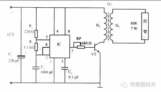
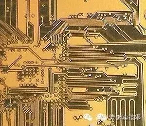
This is mainly because, in the design of the printed circuit board, it is mainly considered whether the distribution and connection of all the components are reasonable. It is necessary to consider factors such as component volume, heat dissipation, anti-interference, anti-coupling, etc., and the printed circuit board designed by combining these factors. From the outside, it is difficult to be completely consistent with the schematic; in reality, it can better realize the function of the circuit.
With the development of science and technology, the production technology of printed circuit boards has now been greatly developed; in addition to single-panel and double-panel, there are many panels, which have been widely used in daily life, industrial production, national defense construction, aerospace industries, and many others. field.
In the four types of circuit diagrams introduced above, the electrical schematic is the most common and most important, able to understand the schematic diagram, it also has a basic grasp of the principle of the circuit, drawing block diagram, design assembly diagrams, plate maps are all compared Easy. It is also very convenient to master the schematics and carry out maintenance and design of electrical appliances. Therefore, the key is to master the schematic. The composition of the circuit diagram: The circuit diagram is mainly composed of four parts: symbol, connection, node, and comment. The symbol of the component represents the component in the actual circuit. Its shape is not necessarily the same as the actual component, or even completely different. However, it generally shows the characteristics of the components, and the number of pins is consistent with the actual components.
The connection shows the wire in the actual circuit. Although it is a line in the schematic diagram, it is not a line but a variety of copper foil blocks in the commonly used printed circuit boards, just like many of the radio schematics. The wiring is not necessarily linear in the printed circuit board diagram, but it may also be a certain shape of copper film.
Nodes indicate the connection between several component pins or several wires. All component pins and wires connected to the node are conductive regardless of the number.
The comments are very important in the circuit diagram. All the words in the circuit diagram can be categorized as comments. A closer look at each of the above diagrams will reveal that there are notes in various places in the circuit diagram. They are used to describe the model, name, etc. of the components.
If you do not know the role of the circuit, you can first analyze the relationship between the input and output signals of the circuit. For example, the law of signal change and the relationship between them, the phase problem is the same phase, or anti-phase. The circuit and composition form is an amplifying circuit, an oscillating circuit, a pulse circuit, or a demodulation circuit.
The personnel of electrical repair and circuit design are all able to get the job done by analyzing the circuit schematic and understanding the function and working principle of the electrical appliance. The function blocks are divided, and the elements of the entire circuit can be grouped according to different functions, so that each function block forms a combination of elements of a specific function, such as a basic amplification circuit, a switching circuit, a waveform conversion circuit, and the like. The circuit diagram reads: When the circuit is analyzed, the actual work of the circuit can be understood by recognizing the symbols of the various circuit components drawn on the drawings and the connections between them. A schematic is a circuit case that embodies the working principle of an electronic circuit.
The PCB diagram is a mapping drawing of the circuit board. It describes the layout of the circuit board and the position of the components in detail.
Looking at the circuit diagram First of all, look at the power supply section to understand what the circuit is doing under the condition of the power supply, AC or DC, single or multiple power supply and voltage levels. After seeing the branch circuit clearly, the first difference is the digital circuit, or the analog circuit, the analog circuit to see the signal acquisition, to figure out the signal source, there are radio frequency, audio, various sensors, instrumentation or other circuits, etc. The analysis signal is exchange, DC or pulse, is a voltage type or current type. Analyze the function of the subsequent circuit and find out whether it is demodulation, amplification, shaping, or compensation. Finally look at the output circuit, whether it is modulation or drive. Digital circuits mainly analyze the logic functions and functions of the circuit.
To understand the circuit board, first of all it is best to be able to understand its electrical schematics (ie, circuit diagrams), to grasp the electronic components and the way it works, to master the normal parameters of some commonly used components and The knowledge of the role played in a normal circuit, and then the analysis of a circuit board (called a printed circuit board), it can quickly understand its working principle and some need to grasp the situation.
Molecular circuit module, and then find the core components of a sub-circuit (of course, be familiar with this component) to find out the electrical connection between the sub-circuit modules, and finally the entire circuit output and input or function.
The whole circuit has a certain function, which is composed of each unit circuit. The unit circuit forms a signal processing branch with certain functions, and then these branch circuits form the whole circuit. First of all, make sure what you see in the circuit diagram is what kind of circuit, is audio, video, digital, or hybrid circuit, and then use the corresponding unit circuit knowledge to interpret these circuits, and from the AC signal level Analysis of the DC level, the DC part of the circuit is the basis for the normal operation of the circuit, the AC signal can be processed after the DC circuit is normal, and the circuit does not have a good DC state and cannot work normally.
Also from the frequency level, the gain level of the amplifier is analyzed. When the signals of different frequencies are processed by the circuit, due to the non-linear elements in the circuit, they will have different processing results for different frequencies. The amplifier also has different signals at different frequencies. With different amplifying capabilities, the circuit will perform targeted processing of the required frequency signal during design, so as to meet the needs of the machine function. Another is to analyze the relationship between the unit circuits, and the relationship between the input and output of the unit circuits.
What happens to the AC signal after passing through these circuits? After understanding the working principle of each branch, we can analyze the working principle of the whole machine, and sometimes there are cross-links between signals in each branch circuit. For example, the line retrace pulse of the TV line output circuit is used for the color decoding circuit. The line output circuit and the color decoding circuit have signals that are connected to each other. At this time, these branches can be understood as another unit circuit, and then They analyze it.
I think there is a sequence problem in this: For example, for high-frequency circuits, the function and input/output relationship of the circuit should be mastered first. After grasping the overall situation, it is like grasping the nose of a cow because although the circuit is different, the device is different, but Their input and output relationship spectrum will not change. Then analyze the basic principles and methods to achieve such functional transformation, specific to part of the analysis. The circuit design is to start by analyzing the circuit schematic, but must first understand the pin and basic role of the required chip, this will help to better understand the working principle of the circuit, so that it can be applied to its own circuit, is conducive to Circuit cutting and expansion.
First of all, there is a general understanding of the circuit schematic, divided into various functional modules, such as power modules, controller modules, memory modules, audio modules, GPRS modules. Each module is analyzed one by one, and at the end of the process, the functions to be realized by the circuit can be generally understood. It is best to master the principles of common or commonly used unit circuits, such as power modules, voltage regulator modules, memory modules, etc., commonly used chips, such as: 7805, 7812 and so on.
It is necessary to divide the circuit that it wants to design into several modules, so that they are designed in different schematics and finally integrated. When there is a signal input in the circuit, what is the voltage at each basic point and what the current is, there must be a rough estimate. For an amplifier, R, L, C circuit depends on whether it is an oscillation circuit, an amplification circuit, or a shaping circuit. After self-analysis and self-design, you will know and master the basic principles of the circuit, and have accumulated experience in designing and debugging later in your design.