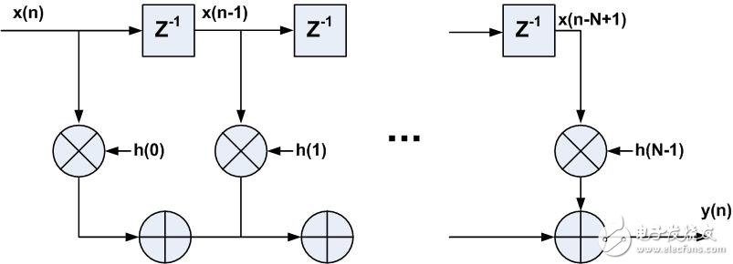
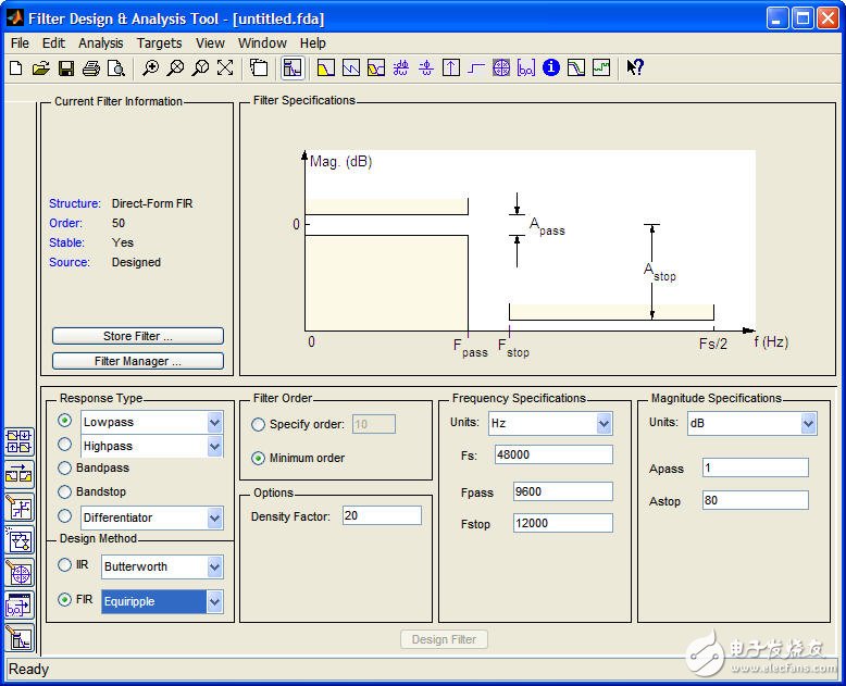
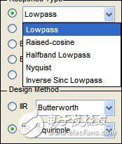
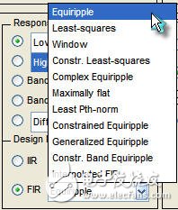
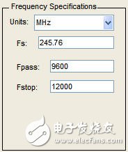
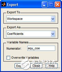
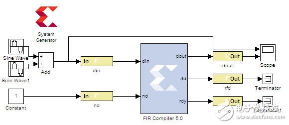
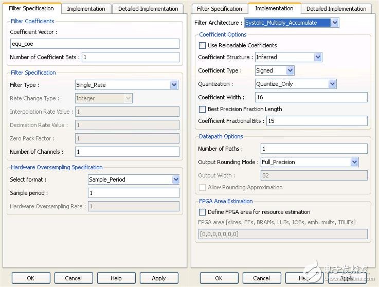
FIR filters are widely used in digital signal processing. The main function is to filter out signals that are not of interest, leaving useful signals. The FIR filter is an all-zero structure, the system is always stable; and it has a linear phase characteristic, and all signals are not distorted in the effective frequency range. In the DDC/DUC module in the wireless communication transceiver, both the decimation and the interpolation need to add a filter to prevent the signal from being aliased on the spectrum. The most typical is to implement a half-band filter using an FIR filter. The FIR filtering process is as follows, where x(n) is the input signal, h(n) is the FIR filter coefficient, y(n) is the filtered signal; N is the number of taps of the FIR filter, and the filter order It is N-1. The implementation structure of the FIR filter in the FPGA can be obtained from the above formula, as shown in FIG. 1, which is mainly composed of a delay unit Z-1, a multiplier and an accumulator. This structure is a direct type FIR filter structure, also called a transverse structure. figure 1 There are many ways to design FIR filters. Matlab software provides a lot of toolboxes for filter design. FDATool is a good tool. As shown in Figure 2, it is the interface of FDATool, which can be directly in Matlab's Command window. Enter the FDATool command to invoke it. figure 2 The filter design first needs to set the parameters: (1) Response Type: Select the type of FIR filter: low pass, high pass, band pass and band stop. As shown in Figure 3, the drop-down option in Lowpass. In the DDC/DUC module design, the Halfband Lowpass type is required for extraction and interpolation, and the Raise-cosine type is required for the channel filter. image 3 (2) Design Method: There are many methods for designing FIR filters, as shown in Figure 4. The most commonly used methods are Window Function, Equiripple and Least-Squares. . Among them, the window function design method is the key point in the school classroom. It is mentioned that the FIR filter will definitely think of hamming and kaiser windows, but it is rarely used in practical applications, because the window function design method is adopted to achieve the desired frequency response. Compared with other methods, the order is often more; and the window function design method generally only designs the filter with reference to the passband wp, the suppression band ws and the ideal gain, but the ripple of the passband and the suppression band is also considered in practical applications. In that case, the equal-ripple design method is very suitable. Figure 4 (3) Filter Order: Set the order of the filter. This option directly affects the performance of the filter. The higher the order, the better the performance, but the resources consumed in the FPGA implementation need to increase. In this setup, there are two options: Specify order and Minimum order. The Specify order is the engineer's own determination of the order of the filter. The Minimum order is the minimum order required for the tool to automatically determine the desired frequency. The options depend on the actual situation. Figure 5 (4) Frequency SpecificaTIon: Set the frequency response parameters, including the sampling frequency Fs, the passband frequency Fpass, and the stopband frequency Fstop. Figure 6 After the parameter setting is completed, FDATool will analyze and generate the filter coefficient. As shown in Figure 7, the corresponding frequency curve of the filter can be obtained, and the filter coefficient can be derived by File-Export, as shown in Fig. 8. Figure 7 Figure 8 To quickly verify the FPGA implementation of the FIR filter, use the Xilinx System Generator tool, as shown in Figure 9 for the FIR filter verification model, where the Matlab simulink module and the Xilinx FPGA module are separated by the Gateway In and Gateway out modules, the matlab simulink module Used to generate a test source, receive and display the filtered waveform. There is also System Generator Token for generating HDL code for the Xilinx FPGA module. Figure 9 The parameter setting of the FIR Compiler 5.0 module is shown in Figure 10. The filter coefficient directly calls the filter coefficient equ_coe generated by FDATool, and the output is full-precision data. Figure 10 The output result is shown in Fig. 11. The upper picture shows the input original waveform, which is formed by superposition of sine waves of two frequency components, the frequencies are 2MHz and 100MHz respectively. After FIR filtering, the 100MHz frequency components are filtered out. Figure 11
For the passed long time, the main sizes of laptops fell into three ones, 13 Inch Budget Laptop For Student, especially elementary or middle school or prefer smaller size; 17.1 inch graphic laptop for the ones prefer higher performance and bigger screen; 15.6 inch Budget Working Laptop for all others left. However, 14 Inch Laptop is becoming the main trend now, 11 Inch Laptop and 10.1 Inch Laptop also available at the market and our store.
14 Inch Gaming Laptop with i3, i5, i7 10th generation is a great choice for those who do heavy jobs and often go to business trip, like interior designers, engineering or architecture students or workers, etc. Of course, 14 Inch Laptop With Graphics Card, 16.1 inch i7 16gb ram 4gb graphics laptop also alternatives.
Of course, other Laptop 14 Inch I5 or 14 Inch To CM Laptop you can see also at this store. To save time, you can contact directly and share exact configuration so that we can provide right and valuable information quickly for you.
Except business, any we can do in China, just let us know also.
Not only want to cooperate, but also hope be your friend in China.
14 Inch Laptop,14 Inch Gaming Laptop,Laptop 14 Inch I5,14 Inch Laptop With Graphics Card,14 Inch To Cm Laptop Henan Shuyi Electronics Co., Ltd. , https://www.shuyicustomlaptop.com
