As shown in the figure, the circuit diagram of the multifunctional call for help. The whole machine is composed of a call for help alarm signal generation circuit, an audio power amplifier circuit, a voice-activated lantern metronome and a changeover switch. Dongguan Metalwork Technology Co., LTD. , http://www.diecast-pro.com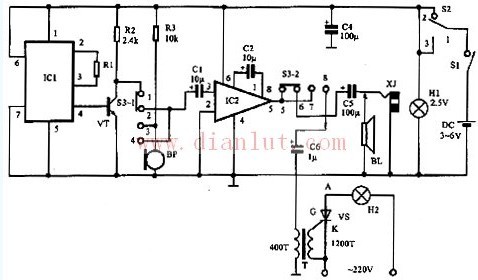
Working principle: When the power switch S1 is closed, the changeover switch S2 is set to 2 digits, and when S3 is set to 1 and 5 digits, the machine is in the state of call for help. The call for help alarm signal generator composed of IC1 music integrated circuit KD9561 is triggered to conduct, the generated alarm signal is preamplified by triode VT (9013), and then amplified by audio power amplifier circuit IC2 (LM386), and the rear stage C5 pushes the speaker (BL , 8 Ω) issued a call for help. When S2 is set to 3, the small bulb H1 is energized and illuminated, and this is the illumination state. When S2 is set to 2 bits and S3 is set to 2 bits, the microphone BP couples the microsonic signal to the IC through the capacitor C1, and it is pronounced through the headphones to play the hearing aid. When the sound is released through the speaker, it can be used. To the sound reinforcement. When S2 is set to 2 bits and S3 is set to 3 bits, the voice or music signal is outputted by the microphone BP, and then amplified by IC2, coupled to the control electrode G of the unidirectional thyristor VS through the transformer T, and triggered. VS turns on with the size of the voice or music signal, and sometimes turns off, causing the lantern H2 to flash. When S2 is set to 2 digits, and the doorbell button line is connected to both ends of S1, the machine can be used as a doorbell. In the circuit, R1 is a tone adjustment resistor, C1 and C5 are coupling capacitors, and C2 is a gain adjustment capacitor of IC2.