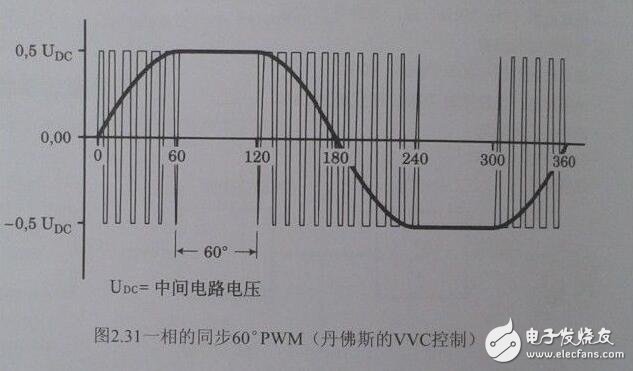
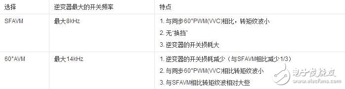
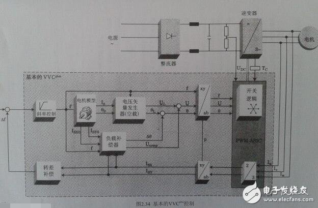
Variable-frequency drive (VFD) is a power control device that controls the AC motor by changing the working frequency of the motor by applying variable frequency technology and microelectronic technology. The frequency converter is mainly composed of rectification (AC to DC), filtering, inverter (DC to AC), braking unit, drive unit, and detection unit micro processing unit. The inverter adjusts the voltage and frequency of the output power supply by the internal IGBT breaking, and supplies the required power supply voltage according to the actual needs of the motor, thereby achieving the purpose of energy saving and speed regulation. In addition, the frequency converter has many protection functions. Such as overcurrent, overvoltage, overload protection and so on. With the continuous improvement of industrial automation, inverters have also been widely used. The power supply we use is divided into AC power supply and DC power supply. Generally, the DC power supply is mostly obtained by AC power supply transformer transformation and rectification and filtering. AC power accounts for about 95% of the total power used by people. Whether it is used in the home or in the factory, single-phase AC power supply and three-phase AC power supply, the voltage and frequency have certain standards according to the regulations of various countries. For example, the direct-user single-phase AC voltage is 220V, three-phase. The voltage of the AC line is 380V and the frequency is 50Hz. The voltage and frequency of the power supply in other countries may be different from the voltage and frequency in China. For example, single-phase 100V/60Hz, three-phase 200V/60Hz, etc., standard voltage and frequency AC power supply. The power source is called power frequency AC. Generally, a device that converts a power frequency alternating current having a constant voltage and frequency into a voltage or a variable frequency alternating current is called a "frequency converter". In order to generate a variable voltage and frequency, the device first converts the alternating current of the power source to direct current (DC), a process called rectification. The general inverter is an inverter power source that inverts the DC power supply to a certain frequency and a certain voltage. For inverters with adjustable inverter frequency and voltage, we call them inverters. The waveform outputted by the inverter is an analog sine wave, which is mainly used for speed regulation of three-phase asynchronous motor, also called frequency converter. For variable frequency inverters with high waveform requirements mainly used in instrumentation testing equipment, the waveform should be sorted to output a standard sine wave, called a variable frequency power supply. The general variable frequency power supply is 15-20 times the price of the inverter. The frequency converter can also be used in home appliances. Among the home appliances that use inverters, there are not only motors (such as air conditioners) but also fluorescent lamps. A frequency converter for motor control that changes both voltage and frequency. However, the inverter used for fluorescent lamps is mainly used to adjust the frequency of power supply. The working principle of the frequency converter is widely used in various fields. For example, the power supply of a computer power supply, in this application, the frequency converter is used to suppress reverse voltage, frequency fluctuations and instantaneous power failure of the power supply. The frequency converter mainly adopts the AC-DC-AC mode (VVVF frequency conversion or vector control frequency conversion). First, the power frequency AC power supply is converted into a DC power source through a rectifier, and then the DC power source is converted into an AC power source whose frequency and voltage can be controlled to be supplied. Electric motor. The frequency converter is mainly composed of rectification (AC to DC), filtering, inverter (DC to AC), braking unit, drive unit, and detection unit micro processing unit. The frequency converter is usually divided into four parts: rectifier unit, high-capacity capacitor, inverter and controller. Rectifier unit: converts AC power with fixed operating frequency to DC power. High-capacity capacitor: Stores the converted power. Inverter: An electronic switch consisting of a high-power switching transistor array that converts direct current into square waves of different frequencies, widths, and amplitudes. Controller: Operates according to the set program, controls the amplitude and pulse width of the output square wave, and superimposes the alternating current into an approximate sine wave to drive the AC motor. The frequency converter is a device that converts alternating current with constant voltage and frequency into alternating current with variable voltage or frequency, and has a wide range of applications in actual production. So what is the working principle of the inverter? The following electrician's house will take you to share it. Its main circuit consists of three parts, namely rectifier, smoothing circuit and inverter, and is generally divided into current type and voltage type. The voltage type is a frequency converter that converts the direct current of the voltage source into an alternating current, and the filtering of the direct current circuit is a capacitor. The current type is a frequency converter that converts the direct current of the current source into an alternating current, and the direct current loop filtering is an inductance. It consists of three parts, which converts the power frequency power supply into a "rectifier" of DC power, absorbs the "flat wave loop" of the voltage ripple generated by the converter and the inverter, and converts the DC power into the "reverse" of the AC power. Transformer." Rectifier Recently used a large number of diode converters, which convert the commercial power supply into a DC power supply. Two sets of transistor converters can also be used to form the inverter, and the regenerative operation can be performed because the power direction is reversible. Flat wave loop The DC voltage rectified by the rectifier contains a ripple voltage of 6 times the frequency of the power supply, and the ripple current generated by the inverter also causes the DC voltage to fluctuate. In order to suppress voltage fluctuations, the ripple voltage (current) is absorbed by the inductor and the capacitor. When the device capacity is small, if the power supply and the main circuit constitute a device with a margin, the inductor can be omitted and a simple smoothing circuit can be used. Inverter In contrast to the rectifier, the inverter converts the DC power to the AC power of the required frequency, and the three switching devices are turned on and off at the determined time to obtain the 3-phase AC output. The switching time and voltage waveforms are shown by taking a voltage type pwm inverter as an example. Control circuit It is a circuit that provides control signals to the main circuit of the asynchronous motor (voltage and frequency adjustable). It has an "arithmetic circuit" of frequency and voltage, a "voltage and current detecting circuit" of the main circuit, and a "speed detecting circuit" of the motor. A "drive circuit" that amplifies the control signal of the arithmetic circuit, and a "protection circuit" of the inverter and the motor. (1) Operation circuit: The external speed and torque commands are compared with the current and voltage signals of the detection circuit to determine the output voltage and frequency of the inverter. (2) Voltage and current detection circuit: It is isolated from the main circuit potential to detect voltage and current. (3) Drive circuit: A circuit that drives the main circuit device. It is isolated from the control circuit to turn the main circuit device on and off. (5) Protection circuit: Detect the voltage, current, etc. of the main circuit. When an abnormality such as overload or overvoltage occurs, in order to prevent damage to the inverter and the asynchronous motor, the inverter is stopped or the voltage and current values ​​are suppressed. The figure above is a schematic diagram of the principle of the inverter control circuit. The upper half is the main circuit and the lower half is the control circuit. Mainly composed of control core CPU, input signal, output signal and panel operation indication signal, memory, LSI circuit. The analog signal of the external potentiometer is sent to the CPU through analog-to-digital conversion to achieve the purpose of speed regulation. The external switching signal is also sent to the control CPU via the NAND gate. control method 1: VVVF is the abbreviation of Variable Voltage and Variable Frequency, which means changing the voltage and changing the frequency, which is called variable voltage frequency conversion. 2: CVCF is the abbreviation of Constant Voltage and Constant Frequency, which means constant voltage, constant frequency, which is what people call constant voltage constant frequency. VVC control principle In VVC, the control circuit uses a mathematical model to calculate the optimum motor excitation for changes in motor load and compensate for the load. In addition, the synchronous 60° PWM method integrated on the ASIC circuit determines the optimum switching time of the inverter semiconductor device (IGBTS). The following principles should be followed to determine the switching time: The largest phase in the value keeps its positive or negative potential constant for 1/6 of a cycle (60°). The other two phases are scaled to keep the output line voltage sinusoidal and reach the desired amplitude (as shown below) Unlike sinusoidal control PWM, VVC operates on the basis of the required digital output voltage. This ensures that the output of the inverter reaches the rated value of the voltage. The motor current is sinusoidal. The operation of the motor is the same as when the motor is directly connected to the mains. Since the constants (stator resistance and inductance) of the motor are taken into account when calculating the optimum output voltage of the frequency converter, optimum motor excitation is obtained. Because the inverter continuously detects the load current, the inverter can adjust the output voltage to match the load, so the motor voltage can adapt to the type of motor and follow the load change. The control principle of VVC+ is to apply the principle of vector modulation to a fixed voltage source PWM inverter. This control is based on an improved motor model that better compensates for load and slip. Because the active and reactive current components are important to the control system, the angle of the control voltage vector can significantly improve the dynamic performance in the 0-12HZ range, while in the standard PWM U/F drive 0-10HZ range There are generally problems. Using the SFAVM or 60° AVM principle to calculate the switching mode of the inverter, the ripple of the air gap torque can be made small (compared to a frequency converter using synchronous PWM). The user can choose his or her favorite working principle, or the inverter automatically selects the control principle based on the temperature of the heat sink. If the temperature is below 75 °C and the SFAVM principle is used for control, the 60° AVM principle is applied when the temperature is above 75 °C. An outline of these two principles is given below: As shown in the figure below, the motor model calculates the nominal no-load values ​​ISX0, Isy0 and I0, θ0 for the load compensator and the voltage vector generator, respectively. Knowing the actual no-load value makes it possible to estimate the load torque of the motor shaft more accurately. Compared with the V/f control, the voltage vector control is advantageous at low speeds, and the dynamic characteristics of the transmission can be significantly improved. In addition, because the control system can better estimate the load torque and give the vector value of voltage and current, the voltage vector control can get a good static characteristic compared with the case of scalar (only size value) control. Desktop Power Adapter,Hp All-In-One Desktop Power Adapter 90W,Laptop Power Adapter Charger,Hp Desktop Power Adapter Guang Er Zhong(Zhaoqing)Electronics Co., Ltd , https://www.poweradapter.com.cn
(4) Speed ​​detection circuit: The signal of the speed detector (tg, plg, etc.) mounted on the asynchronous motor shaft machine is sent to the calculation circuit as a speed signal, and the motor can be operated at the command speed according to the command and calculation. 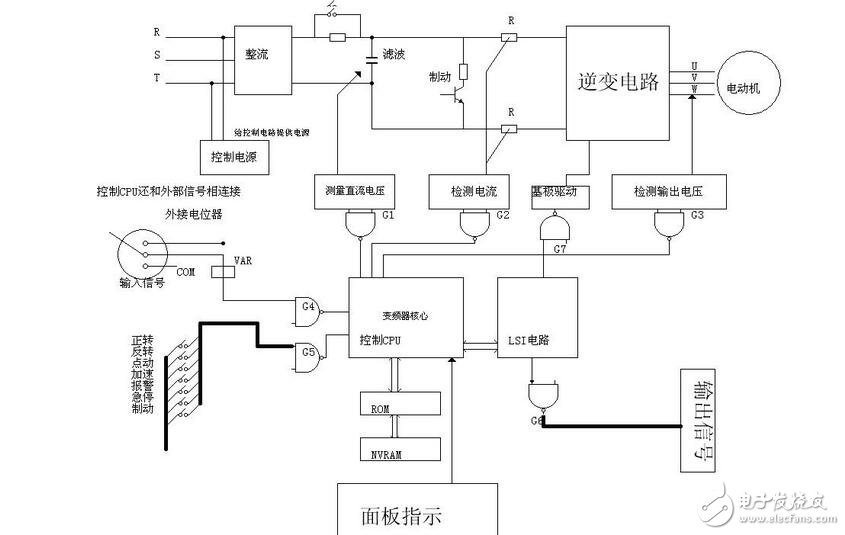
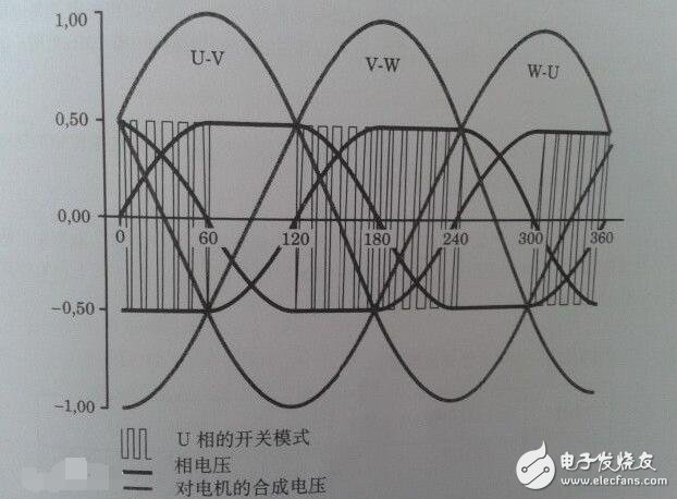
The basic composition of the inverter and its working principle
Desktop Power Adapter is a type of power supply unit specifically designed for desktop environments or similar settings. It typically features a larger form factor and higher power output capabilities to accommodate the greater electrical demands of desktop devices such as computers, monitors, printers, and other electronic equipment.
Desktop Power Adapters find widespread use in powering a range of desktop equipment, including but not limited to:
Computers and Accessories: Desktop computers, monitors, printers, and other peripherals.
Audio-Visual Equipment: Sound systems, projectors, and other A/V gear.
Industrial Automation: Powering machinery and devices in industrial settings.
Other Desktop Devices: Security cameras, routers, and other electronics requiring a stable power source.
Selection Criteria