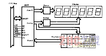
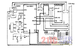
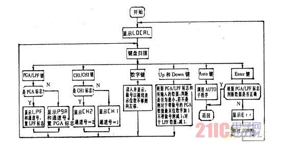
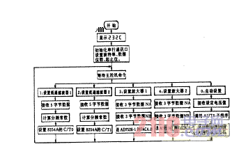
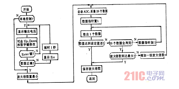
The analog signal output by the sensor generally needs to be amplified, attenuated, and filtered before being sent to the ADC for analog/digital conversion. In the fields of automatic control and smart meters, it is required that this process can be controlled by software, automatically adjust the amplification or attenuation, set the cut-off frequency of the low-pass filter, and transmit these parameters to the CPU to correct the measurement results. ; Most of the finished data acquisition boards on the market do not have the preprocessing function of analog signals, and manual control of amplification and filtering devices must be connected when used, which cannot be automated. The author developed this intelligent analog signal preprocessing system based on single-chip microcomputer to solve these problems. Of course, the system can also be used as a general amplifier and filter. Figure 1 is a simplified diagram of the analog signal preprocessing circuit. The program-controlled amplifier/attenuator is composed of the dual current output DAC chip AD7528 and the operational amplifier. The principle is to use the R-2R resistor network inside the DAC, one DAC as the input resistance of the operational amplifier, and the other as the feedback resistance. The equivalent resistance of R-2R can be written as: RDACA=256RLDA/NA; RDACB=256RLDB/NB Among them, RLDA and RLDB are the R-2R ladder network resistances of DAC A and B, respectively, and NA and NB are decimal DAC input numbers (1 to 255). The gain of the circuit is: Vout/Vin=-(RLDB/RLDA)×(NA/NB). AD7528 is a double precision matched DAC, where RLDB=RLDA, so the gain of the circuit is: Vout/Vin=-NA/NB, it can be seen that it is completely determined by the input digital quantity. Therefore, this circuit and does not require an external precision resistor to obtain accurate magnification. The amplification range is 1/255~255 (-48dB~+48dB). The chip select signals of the two AD7528s are provided separately by the decoder, so the amplification factor of the dual channels can be set independently. The amplified or attenuated analog signal is buffered and then input to the switched capacitor filter RF5609. RF5609 is a seven-pole, six-zero elliptic function low-pass filter, the cut-off frequency is one hundredth of the working clock frequency, the variable range is 0.1Hz~25kHz, the fluctuation within the passband is 0.2dB, and the stopband attenuation is 100dB/time Frequency range. The MAX291~295 series switched capacitor low-pass filters of MAXIM Company can also be used. The working clock of the filter is provided by the programmable timer/counter 8254A. The 8MHz crystal provides the input clock for 8254A through the oscillator circuit. The 8254A works in the mode of square wave generator. OUT0 and OUT1 provide the filter working clocks of channels 1 and 2 respectively. Therefore, the two channels can be set to the same or different low-pass Cut-off frequency. The RC circuit after the filter is used to eliminate the interference caused by the working clock. The preprocessed analog signal is output after the buffer. Figure 1 Analog signal preprocessing Figure 2 shows the keyboard and display circuit, which is driven by 8255 PA and PB to control a 6-digit LED digital display; PA and PC control a keyboard with 18 keys, including number keys "0-9", division sign "÷", Upward "Up", downward "Down", local/remote "Local/Remote", amplifier/filter "PGA/LPF", channel "Channel1/Channel2", automatic setting "Auto" and enter key "Enter" . Figure 2 Keyboard and display Figure 3 shows the CPU circuit. Using 8031CPU, EPRO-M2764 as program memory, it can also be replaced by 8751. There is no large amount of data to be stored during the operation of the system, so there is no data storage. The three address lines A13~A15 are decoded by 74LS138 decoder to form CS0~CS4 chip selection lines, which control 8254, two AD7528, 8255 and DAC-0808 respectively. The purpose of setting the DAC is that when the system is set to "automatic setting", the system can automatically adjust the amplification factor of the amplifier according to the required output analog signal level or ADC half-scale value. In addition, an RS232 transceiver circuit is set up for remote control. Figure 3 CPU circuit The main software can be divided into three parts: "local control" software, "remote control" software and "automatic setting" software. Figure 4 shows the "local control" process. "LDCAL" means that the system is in the "local control" state. The user can set the double-channel magnification and the cut-off frequency of the low-pass filter through the keyboard. "Attenuation 1/200" is displayed as "1-200", and the input is 1÷200. Figure 4 Flow chart of "local control" Figure 5 shows the "remote control" process. "232C" means that the system is controlled by the main controller through the RS232 serial port. Only recognize the 5 commands sent by the host computer in the form of numbers 0 to 4, and take corresponding actions. When the host computer requires the system to "automatically set", after the magnification is automatically set, the set value will be sent to the host computer for calibration. Note that this system cannot automatically set the cut-off frequency of the low-pass filter, only the default value or the value set before this can be used. Figure 5 "Remote Control" flow chart Figure 6 shows the "automatic setting" process. According to the amplifier output voltage sent by the master computer or set by the keyboard and the ADC0800 range (±10V), the value that needs to be taken can be calculated. For example, if the output voltage is set to 2500mV, the collected data should be greater than or equal to 192 for positive voltage and less than or equal to 64 for negative voltage. If it is not reached, increase the magnification by one more level and continue to collect and judge. Although the magnification may be increased in steps of 1/255, in order to speed up the speed, it can be increased in larger steps or in a proportional sequence. Figure 6 Flow chart of "Auto Setup" This system organically combines the preprocessing of the analog signal with the single-chip microcomputer, and realizes the intelligent processing of the analog signal with its perfect control function. It has been used in the research and development of equipment transformation, automatic control, and intelligent instrumentation. Played an excellent role. Ningbo Autrends International Trade Co.,Ltd. , https://www.vapee-cigarettes.com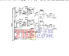
Detailed design of an intelligent analog signal preprocessing system based on single chip microcomputer
1 Introduction